
HVAC Design for Healthcare in Indian Climates
An Architect's Working Reference — ASHRAE 170-2021 Decoded, Indian Climate Adaptations (Warm-Humid, Composite, Temperate, Cold), Pressure Cascades, OT/ICU/Isolation/BMT Specifics, 100% Fresh-Air vs Recirculation, HEPA Terminal Modules, BMS Integration, and the Healthcare HVAC Architectural Toolkit
Healthcare HVAC is the most demanding HVAC application in any built environment. It must control temperature, humidity, air cleanliness, and pressure simultaneously across a wide range of room types — from a 20°C operating theatre at 25 ACH and HEPA H13 filtration with positive pressure to a 26°C wardroom at 4 ACH with no filtration to a negative-pressure isolation room at 12 ACH with HEPA exhaust to roof. Each room type has its own specification; each specification must be maintained continuously; and the failure of any room type can have direct clinical consequences — surgical site infection, cross-contamination, isolation breach, patient sleep loss, staff fatigue. The architect's role in healthcare HVAC is not to engineer the system but to provision the building for it: floor-to-floor heights, plant rooms, shaft locations, fire-damper provisions, BMS integration, monitoring infrastructure.
This guide is the seventh in the design-focused series. It assumes the reader has read the preceding articles, particularly the pillar regulatory reference, the NBC Group C-1 reference, the NABH guide, the OT design guide, and the ICU design guide.
The guide covers ASHRAE 170-2021 in working detail, the Indian climate adaptations the international standard does not address, the pressure-cascade discipline that separates well-engineered hospitals from problematic ones, the architectural provisioning that supports HVAC, and the most common Indian-context HVAC design errors that the architect can pre-empt.
"The hospital HVAC is the most expensive thing the architect cannot see, and the most consequential. Every patient depends on air she does not know is being cleaned, conditioned, and pressurised on her behalf." — Dr. Reji Iype, hospital infection-control physician, paraphrased from a 2018 NABH conference
"In Indian climate, every hospital HVAC must do four things at once — cool, dehumidify, filter, and pressurise. The OT does it well; the ward usually doesn't. The patient feels the difference." — Senior HVAC consultant on Indian healthcare projects, paraphrased
1. ASHRAE 170-2021 — The International Standard
ASHRAE Standard 170 (Ventilation of Healthcare Facilities) is the international reference for healthcare HVAC. The 2021 edition is the current version. NABH 5th edition adopts ASHRAE 170 essentially verbatim. The architect's task is to coordinate building provisions with the standard.
Headline ASHRAE 170 specifications by space
| Space | Min ACH | Min OA ACH | Pressure | Filtration | RH (%) | Temp (°C) |
|---|---|---|---|---|---|---|
| Class A OT | 20 | 4 | + | HEPA H13 | 30–60 | 18–24 |
| Class B OT (orthopaedic / cardiac) | 25 | 4 | + | HEPA H13 + laminar | 30–60 | 18–24 |
| Class C OT (joint replacement / neuro) | 25 + laminar | 4 | + | HEPA H14 ULPA | 30–60 | 18–22 |
| PACU / Recovery | 6 | 2 | 0 | MERV 14 | 30–60 | 21–24 |
| Pre-anaesthesia | 6 | 2 | 0 | MERV 14 | 30–60 | 21–24 |
| ICU general | 6 | 2 | + | MERV 14 (HEPA preferred) | 30–60 | 21–24 |
| NICU | 6 | 2 | + | HEPA H13 | 45–60 | 22–26 |
| PICU | 6 | 2 | + | MERV 14 | 30–60 | 21–24 |
| BMT positive isolation | 12 | 2 | ++ | HEPA H14 + ULPA | 30–60 | 21–24 |
| Isolation negative | 12 | 2 | −− | HEPA H14 exhaust | 30–60 | 21–24 |
| Anteroom (BMT) | 10 | 2 | + (intermediate) | HEPA H13 | 30–60 | 21–24 |
| Anteroom (isolation) | 10 | 2 | − (intermediate) | HEPA H13 | 30–60 | 21–24 |
| IPD ward | 4 | 2 | 0 | MERV 8 | 30–60 | 21–26 |
| OPD consultation | 4 | 2 | 0 | MERV 8 | 30–60 | 22–26 |
| OPD waiting | 6 | 2 | 0 | MERV 8 | — | 22–26 |
| ED triage / waiting | 6 | 2 | 0 | MERV 13 | — | 22–26 |
| ED resuscitation | 12 | 2 | + | MERV 14 | 30–60 | 21–24 |
| Radiology | 6 | 2 | 0 | MERV 8 | — | 21–24 |
| MRI | 4 | 2 | 0 | MERV 8 | 40–60 | 18–22 |
| CT | 6 | 2 | 0 | MERV 8 | 30–60 | 18–24 |
| CSSD clean side | 10 | 2 | + | HEPA H13 | 30–60 | 18–22 |
| CSSD dirty side | 10 | 2 | − | HEPA H13 | 30–60 | 18–22 |
| Pharmacy clean room | 12 | 2 | + | HEPA H13 | 30–60 | 18–22 |
| Lab — general | 6 | 2 | − | MERV 14 | 30–60 | 21–24 |
| Microbiology BSL-2 | 12 | 2 | − | HEPA H14 exhaust | 30–60 | 21–24 |
| Microbiology BSL-3 | 12+ | 2 | −− | HEPA H14 dual exhaust | 30–60 | 21–24 |
| Mortuary cold | 10 | 2 | − | MERV 8 | — | 2–8 |
| Kitchen | 10 | 2 | − | MERV 8 | — | 22–28 |
| Laundry — soiled | 10 | 2 | − | MERV 8 | — | 22–28 |
| Laundry — clean | 10 | 2 | + | MERV 8 | — | 22–28 |
The architect provisions the building for these specifications — particularly plant-room location and size, shaft sizing, floor-to-floor height at OT/ICU/isolation, and damper coordination at fire-rated walls.
2. Indian Climate Zones — The Adaptation Required
ASHRAE 170 is climate-agnostic, calibrated for moderate North American climates. Indian climate zones impose specific HVAC adaptations.
Climate zones (IMAC / ECBC framework)
| Zone | Cities | Key Challenge | HVAC Implication |
|---|---|---|---|
| Hot-dry | Jaipur, Ahmedabad, Jodhpur | Extreme summer heat; low humidity | High cooling load; lower latent load |
| Warm-humid | Mumbai, Goa, Chennai, Kochi | Monsoon humidity 80–90%; moderate heat | High latent (dehumidification) load — most challenging |
| Composite | Delhi, Bengaluru, Hyderabad, Pune | All seasons; wide range | All-season HVAC; balanced load |
| Temperate | Bengaluru, parts of Kerala, NE | Mild year-round | Lower cooling demand; ventilation-led |
| Cold | Shimla, Manali, Srinagar | Heating dominant | Heating + winter air control |
Warm-humid challenge — the architect's adaptation
Warm-humid is the most challenging zone for healthcare HVAC. RH at 60% (ASHRAE 170 max) is hard to maintain when ambient RH is 85% and outside air is 4 ACH minimum.
| Issue | Architectural / HVAC Response |
|---|---|
| Latent load is 50–60% of total cooling | Dedicated outside air system (DOAS) for treating fresh air; reheat; desiccant wheels in some cases |
| Mould growth in HVAC condensate | Drain-pan disinfection; UV-C in AHU |
| Building envelope condensation | Vapour barrier; thermal bridge analysis |
| Condensation on cold-water pipes / ducts | Insulation thickness sized for warm-humid; vapour-tight |
| RH spike during monsoon | Redundant dehumidification |
| Plant room humidity | Ventilation; insulation |
Composite climate — the architect's adaptation
Composite climate (Delhi, Bengaluru, Pune) sees temperature swings 5°C to 45°C across the year and humidity 30% to 85%. HVAC must handle peak summer cooling, monsoon dehumidification, and winter heating (some zones).
| Issue | Response |
|---|---|
| Cooling-heating switchover | 4-pipe fan-coil systems for OT, ICU; 2-pipe with reheat for general |
| Wide temperature swing | Modulating chillers, reheat |
| Dust loading in summer | Higher MERV pre-filters |
| Winter dryness | Humidification (especially OT, ICU) |
Hot-dry climate
| Issue | Response |
|---|---|
| Peak cooling load | Higher chiller capacity; thermal mass envelope helps |
| Lower latent load | Less dehumidification needed; reheat may not be needed |
| Dust storms | Pre-filter access; sand-trap |
| Diurnal swing | Night flushing through operable windows (in non-clinical areas) |
Temperate climate
| Issue | Response |
|---|---|
| Low cooling load | Smaller equipment; ventilation-led design |
| High year-round RH | Some dehumidification needed |
| Outdoor air can supplement | Operable windows in non-clinical |
Cold climate
| Issue | Response |
|---|---|
| Heating dominates | Boilers, district heat, radiant floor (some applications) |
| Cold OA at 0–10°C | Pre-heat outside air; energy recovery |
| Frost on coils | Defrost cycles |
| Indoor humidity drop | Humidification |
3. The Pressure Cascade in Architectural Plan
Pressure differentials are maintained by air-handling design and architectural details — door undercut, damper, sealing, BMS.
| Adjacency | Pressure Differential (Pa) | Architectural Detail |
|---|---|---|
| OT to corridor | + 25 | Door gasket; overflow via undercut |
| ICU to corridor | + 5 | Standard door |
| Anteroom to corridor (isolation) | − 5 | Self-close door |
| Isolation room to anteroom | − 5 | Self-close door + sealed gasket |
| BMT room to anteroom | + 5 | Self-close door |
| Anteroom (BMT) to corridor | + 2 | Self-close door |
| Corridor to public lobby | 0 / neutral | Standard |
| Soiled utility to corridor | − 5 | Self-close |
| Sterile store to corridor | + 5 | Self-close |
Pressure monitoring infrastructure:
- Continuous monitor at every OT door, every isolation door, every BMT door
- BMS-integrated for alarm
- Visible to staff entering room
- Calibrated annually
4. Air Handling Units — Sizing and Plant Rooms
| Hospital Size | Total AHU Count | Major OT AHUs | Plant Room Allocation |
|---|---|---|---|
| 30-bed nursing home | 4–6 AHUs | 1 dedicated OT AHU | 60–90 m² |
| 100-bed hospital | 12–18 AHUs | 4–6 dedicated OT/ICU AHUs | 250–350 m² |
| 200-bed hospital | 25–35 AHUs | 8–12 dedicated | 500–700 m² |
| 500-bed hospital | 60–80 AHUs | 20–30 dedicated | 1,200–1,600 m² |
AHU placement:
- Dedicated AHU per OT (or max 2 OT shared) — preferred for cross-contamination prevention
- Dedicated AHU for isolation room cluster — required
- Zone AHU for ward floors — typical (1 AHU per ward floor or per wing)
- Service AHU for plant areas, kitchen, laundry — separate
Plant room location:
- Top floor / mechanical floor — preferred for ducting access
- Basement / sub-station floor — alternative; longer vertical ducts
- Roof penthouse — possible but structural / fire access
- Distributed plant rooms per zone — for large hospitals
5. Filtration — MERV, HEPA, ULPA
| Filter Class | Efficiency | Application |
|---|---|---|
| MERV 8 | 70% at 3–10 µm | General areas, OPD, IPD, kitchen, laundry |
| MERV 13 | 85% at 1–3 µm; 50% at 0.3–1 µm | OPD waiting, ED, lobby; minimum for COVID protocol |
| MERV 14 | 90% at 1–3 µm; 75% at 0.3–1 µm | ICU, recovery, lab |
| HEPA H13 | 99.95% at 0.3 µm | OT, BMT, isolation, CSSD clean, pharmacy clean |
| HEPA H14 | 99.995% at 0.3 µm | Class C OT (joint), BMT, BSL-3 |
| ULPA U15 / U16 | 99.9995% / 99.99995% at 0.12 µm | Specialised cleanrooms, rare in hospitals |
Architectural integration:
- HEPA terminal modules sized at ceiling — typically 600 × 1200 mm, 2.4 mm thick filter cartridge
- AHU pre-filter + final filter sequence — pre-filter (MERV 8) to protect HEPA
- Filter access panels — at AHU and at ceiling in OT/ICU
- Filter testing protocol — DOP / PAO test annually
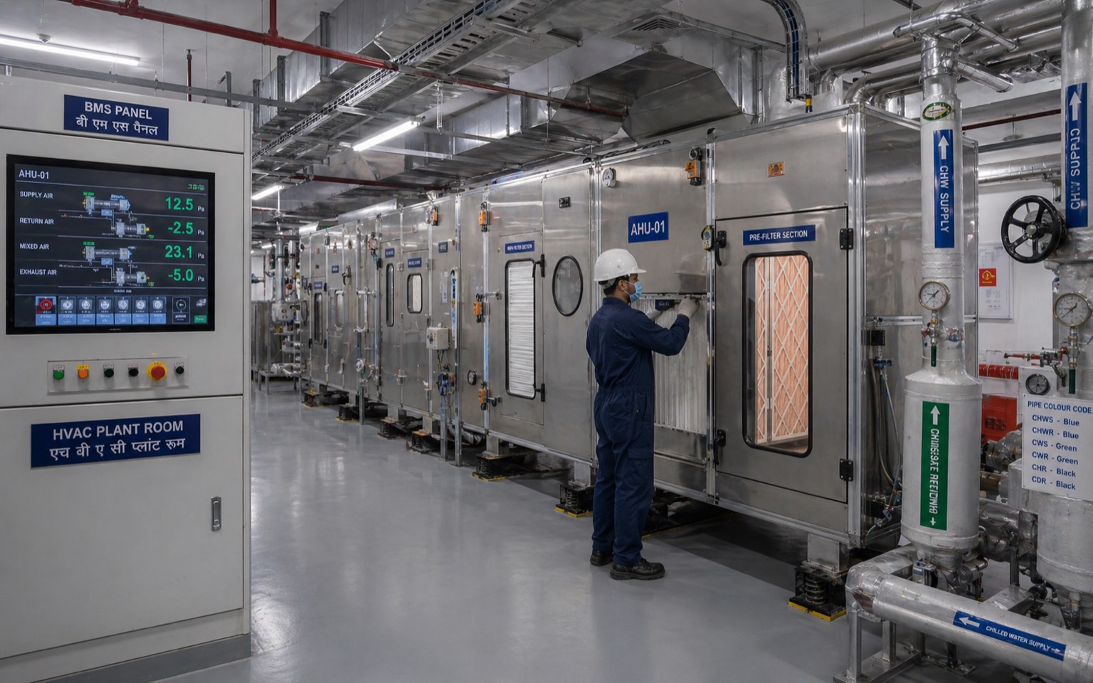
6. Building Management System (BMS) Integration
Modern hospital HVAC requires BMS integration for monitoring, control, and alarm.
| BMS Function | HVAC Integration |
|---|---|
| Real-time pressure monitoring | OT, ICU, isolation, BMT |
| Temperature / humidity logging | All clinical zones |
| Alarm on parameter excursion | Email, SMS, panel |
| Filter pressure-drop monitoring | AHU health |
| Fire alarm integration | HVAC shutdown on fire; smoke damper closure |
| Lift / access control integration | Coordinated emergency response |
| Energy monitoring | kW per space; benchmarking |
| Maintenance scheduling | Preventive maintenance per asset |
| Trend analysis | Long-term performance |
| Reporting | NABH compliance evidence |
The BMS is the architectural / engineering bridge that turns a complex HVAC system into a manageable infrastructure. Its specification is part of the architect's coordination with MEP consultants.
7. Architectural Provisioning for Hospital HVAC
| Architectural Element | Specification |
|---|---|
| Floor-to-floor — OT level | 4.2–4.5 m (3.0 m clear OT + 1.4 m plant ceiling void) |
| Floor-to-floor — ICU level | 4.0 m typical |
| Floor-to-floor — IPD ward | 3.5–3.8 m |
| Plant ceiling void — OT | ≥ 1.4 m |
| Plant ceiling void — ICU | ≥ 1.0 m |
| Plant ceiling void — IPD | ≥ 0.6 m |
| Service shaft — vertical | Per zone; sized for AHU + return + chilled water + steam |
| Plant room — AHU per OT cluster | 30 m² per OT |
| Plant room — AHU per ward floor | 25–40 m² per ward |
| Cooling tower / chiller plant | At-grade or basement; structural; condensate drainage |
| Boiler / steam plant (if used) | Basement or service block; chimney |
| Outside air intake | Above-grade; away from exhaust; bird-screen |
| Exhaust discharge | Roof; > 3 m horizontal separation from intake |
| Structural — equipment loading | Roof / floor for chillers, cooling towers, AHUs |
| Acoustic — plant room separation | Vibration isolators; acoustic walls |
8. The Architect's Healthcare HVAC Toolkit
| # | Step | Output |
|---|---|---|
| 1 | Climate zone audit | HVAC strategy adapted to climate |
| 2 | Programme review — ACH and pressure schedule per space | HVAC schedule |
| 3 | OT count and class — AHU dedicated decision | OT plant strategy |
| 4 | Isolation room count and location | Negative-pressure schedule |
| 5 | BMT cluster (if tertiary) | Positive-pressure cluster |
| 6 | Plant room sizing and location | Plant room allocation |
| 7 | Floor-to-floor heights — OT, ICU, ward | Section adjustments |
| 8 | Service shaft sizing | Riser allocation |
| 9 | Filtration strategy — pre-filter + HEPA / ULPA | Filter schedule |
| 10 | Pressure monitoring infrastructure — at every OT, isolation, BMT | Monitoring schedule |
| 11 | BMS integration brief | BMS scope |
| 12 | Smoke / fire damper coordination at fire walls | Damper schedule |
| 13 | DOAS / dedicated outside-air strategy (warm-humid) | OA system |
| 14 | Commissioning protocol — pressure, ACH, HEPA leak test | Commissioning schedule |
| 15 | Maintenance access — filter replacement, coil cleaning, drain pan | Access provision |
9. Common HVAC Design Failure Modes
| # | Failure | Prevention |
|---|---|---|
| 1 | Shared AHU for 4+ OT | Dedicated AHU per OT |
| 2 | OT plant ceiling void < 1.4 m | 4.2 m floor-to-floor at OT |
| 3 | Pressure cascade not measurable | Continuous monitor at every critical door |
| 4 | DOAS / dedicated outside air absent in warm-humid | Specify DOAS at concept |
| 5 | RH not maintained < 60% in monsoon | Reheat / desiccant strategy |
| 6 | HEPA terminal module access blocked | Designed access panel |
| 7 | Smoke damper at fire wall absent | Damper schedule with fire-rated wall |
| 8 | HVAC return path through return-air ceiling void | Ducted return at OT/ICU |
| 9 | Outside-air intake near exhaust | 3 m + horizontal separation |
| 10 | Plant room undersized | Sizing per AHU count; adequate maintenance access |
| 11 | Vibration isolation absent | Cooling tower / chiller / AHU on isolators |
| 12 | Acoustic — patient-room HVAC noise > 40 dBA | Sized AHU at low velocity; lined ducts |
| 13 | Filter access requires invasive removal | Front-loadable AHU |
| 14 | Condensate drain pan unmaintained | Annual disinfection; UV-C |
| 15 | BMS integration absent | BMS scope at MEP consultancy |
References
- ASHRAE (2021) Standard 170-2021: Ventilation of Health Care Facilities. Atlanta: ASHRAE.
- ASHRAE (2019) ASHRAE Handbook — HVAC Applications: Health-Care Facilities. Atlanta: ASHRAE.
- Bureau of Energy Efficiency (2017) Energy Conservation Building Code 2017. New Delhi: Ministry of Power.
- Bureau of Indian Standards (2016) National Building Code of India 2016, Part 8 — Building Services. New Delhi: BIS.
- Bureau of Indian Standards (2003) IS 7902: Pipeline Distribution System for Medical Gases. New Delhi: BIS.
- Carnino, J., DiBerardinis, L. and Khairallah, J. (2010) 'HVAC strategies for hospitals', ASHRAE Journal, 52(9), pp. 50–58.
- Chow, T.T., Lin, Z. and Bai, W. (2006) 'The integrated effect of medical lamp position and diffuser discharge velocity on ultra-clean ventilation performance in an operating theatre', Indoor and Built Environment, 15(4), pp. 315–331.
- Dharan, S. and Pittet, D. (2002) 'Environmental controls in operating theatres', Journal of Hospital Infection, 51(2), pp. 79–84.
- Facility Guidelines Institute (2022) Guidelines for Design and Construction of Hospitals. St. Louis: FGI.
- Fennelly, K.P. (2020) 'Particle sizes of infectious aerosols: implications for infection control', The Lancet Respiratory Medicine, 8(9), pp. 914–924.
- Gola, M., Settimo, G. and Capolongo, S. (2019) 'Indoor air quality in inpatient environments', International Journal of Environmental Research and Public Health, 16(14), p. 2473.
- Klote, J.H. and Milke, J.A. (2002) Principles of Smoke Management. Atlanta: ASHRAE.
- Manu, S., Shukla, Y., Rawal, R., Thomas, L.E. and de Dear, R. (2016) 'Field studies of thermal comfort across multiple climate zones for the subcontinent: India Model for Adaptive Comfort (IMAC)', Building and Environment, 98, pp. 55–70.
- NABH (2020) Standards for Hospitals, 5th Edition. New Delhi: NABH.
- Sehulster, L. and Chinn, R.Y.W. (2003) 'Guidelines for environmental infection control in health-care facilities', MMWR Recommendations and Reports, 52(RR-10), pp. 1–42.
- Stocks, G.W., O'Connor, D.P., Self, S.D., Marcek, G.A. and Thompson, B.L. (2011) 'Directed air flow to reduce airborne particulate and bacterial contamination', Journal of Arthroplasty, 26(5), pp. 771–776.
- Tang, J.W., Marr, L.C., Li, Y. and Dancer, S.J. (2021) 'COVID-19 has redefined airborne transmission', BMJ, 373, p. n913.
- World Health Organization (2009) Natural Ventilation for Infection Control in Health-Care Settings. Geneva: WHO.
Author's Note: Healthcare HVAC is the most consequential service the architect provisions but does not personally design. The architect's role is to coordinate with the MEP consultant from the brief stage and ensure that building decisions — floor-to-floor heights, plant rooms, shafts, dampers — support the HVAC strategy rather than constrain it. The Indian climate adds challenges that international standards do not address — particularly warm-humid latent load and monsoon RH excursions. The architect who internalises both the ASHRAE 170 framework and the Indian climate adaptation produces hospitals that perform clinically and operationally; the architect who treats HVAC as a downstream MEP problem produces hospitals that fail at the second monsoon. The next guide in this series covers medical gases, plumbing, and electrical infrastructure — the supporting services architecture.
Disclaimer: This article is for informational and educational purposes only and does not constitute professional architectural or engineering advice. HVAC design depends on specific project parameters and must be done by qualified MEP engineers in coordination with the architect and clinical team. Studio Matrx, its authors, and contributors accept no liability for decisions made on the basis of the information in this guide.
Export this guide
Related Tools — Try Free
Cross-Ventilation Analyzer
Estimate airflow and air changes per hour (ACH) from room size, window areas, layout, and local wind — with NBC 2016 Part 8 compliance check.
Ventilation CalculatorMonsoon-Readiness Checklist
Pre-rain home audit across 9 categories — terrace, drains, waterproofing, electrical, HVAC, pest, vehicles, documents.
Seasonal AuditProperty Tax Calculator — 10 Indian Cities
Estimate annual municipal property tax across BBMP / MCD / MCGM / GHMC / GCC / KMC / PMC / AMC / TMC / PCMC — with self-occupied, tenanted, and age-rebate adjustments.
Property Tax